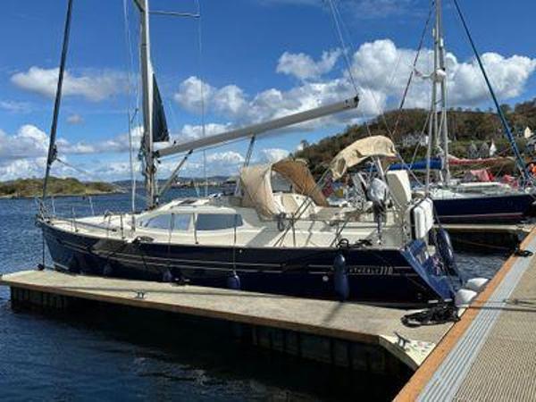
Schooner Goleta
En venta por
XPresentado por:
Barcos Nautica
España
| Marca | Schooner |
|---|---|
| Tipo | Goleta |
| Construcción | 2014 |
| Estado del barco | Usado |
| Precio | US$14.900.000 |
| Clase de oferta | Vela |
| Categoría | Crucero |
| Eslora | 52.55 m |
| Combustible | Diesel |
| Material del casco | Otro |
| Ubicación de la embarcación | buenos aires, Argentina |
| Eslora total | 52.55 m |
|---|---|
| Manga | 8.67 m |
| Calado máximo | 3.81 m |
| Combustible | Diesel |
|---|
| Astillero | Astilleros Buquebus |
|---|---|
| WC invitados | 8 |
Descripción
BArco en CARBONO, mas grande fabricado en America
The largest carbon sailboat manufactured in America
Doña Francisca Yacht length 172´(52,43m) Build 2014/2024
Comentarios/ Comments
Esta, es la construcción del yate más grande de Latinoamérica, en fibra de carbono,
This is the construction of a larger yacht in Latin America and the largest carbon fiber
Un casco significativo de fibra de carbono / Epoxi-infusión
An extraordinary carbon fiber hull with epoxy infusion yachts
El carbono fue el material elegido para su construcción, porque entre los beneficios de este material está en aumentar la relación lastre / desplazamiento,
Carbon was the material chosen for its construction, because among the benefits of this material is to increase the ballast / displacement ratio,
Se solicita que el yate, sea capaz de navegar en aguas poco profundas, incluido el Río de la Plata.
The yacht is requested to be able to navigate in shallow waters, including the Río de la Plata
La quilla es del tipo "T" con un centro de gravedad muy bajo que ayuda a mantener todo su plan de navegación.
The keel is of type "T" with a very low center of gravity that helps keep your entire navigation plan.
El mástil es producido por King Composite. Debido a sus excelentes resultados en el Germanischer Lloyd Certificate
Carbo-Link es actualmente el único fabricante de aparejos de carbono capaz de proporcionar cables de carbón sólido hasta cargas de trabajo de 100 toneladas, lo que convierte a Carbo-Link en el principal proveedor de aparejos de carbono para superyates.
The mast is produced by King Composite. Due to their excellent results in the Germanischer Lloyd Certificate, Carbo-Link is currently the only carbon rigging manufacturer able to provide solid carbon cables up to working loads of 100 tons making Carbo-Link the premier supplier of carbon rigging for superyachts.
Velero del siglo XIX con tecnología del siglo XXI
ACTUALMENTE ES CASCO BLANCO Y SE HA LOGRADO BAJAR LA TEMPERATURA INTERIOR DEL BARCO
19th century sailboat with 21st century technology
CURRENTLY IS A WHITE HELMET AND THE INTERIOR TEMPERATURE OF THE BOAT HAS BEEN DECREASED
Su electrónica es de la última generación para la navegación.
La goleta, comenzó a construirse hace cuatro años y tres meses, recordó su propietario (1 de febrero del 2015)
La embarcación es la síntesis de la mejor arquitectura naval que combina la excelencia marinera con una perfección absoluta en materia de comodidades para el propietario y sus marineros.
Las jarcias de fibra de carbono permiten ahorrar una tonelada y media de peso en comparación con las elaboradas en base a materiales más convencionales.
Para la construcción del casco debió obtener una autorización del gobierno de Estados Unidos para la compra de fibra de carbono.
Timber: Teak and Walnut
Your electronics is the latest generation for navigation.
The schooner, began to be built four years and three months ago, recalled its owner (February 1, 2015)
The boat is the synthesis of the best naval architecture that combines marine excellence with absolute perfection in terms of comfort for the owner and his sailors.
The use of modern elements allows the boat to save weight.
The carbon fiber rigs allow to save a ton and a half of weight in comparison with those made on the basis of more conventional materials.
For the construction of the helmet, he had to obtain an authorization from the United States government for the purchase of carbon fiber.
Empresa española fabrica parte de las escotillas de cubierta en carbono, así como la jarcia de labor y su diseño en colaboración con una empresa italiana
Su instalación es enrasada y ajustadas a la curvatura de la cubierta
El diseño en 3D, los moldes por control numérico, laminado por infusión y curado en un horno especial.
También son diseñadores de la Jarcia fija y de labor: drizas, escotas, burdas.
La escota de vela mayor tiene una carga de trabajo de 16 toneladas y el Génova de 15 toneladas
Spanish company manufactures part of the roof hatches in carbon, as well as the rigging of labor and its design in collaboration with Italian company
Its installation is flush and adjusted to the curvature of the roof
The 3D design, the molds by numerical control, laminated by infusion and curing in a special oven.
They are also designers of the fixed and working rigging: halyards, sheets, coarse.
The main sail sheet has a workload of 16 tons and the Genoa of 15 tons
Extras
Length Over All: 52.50m / 172,24 feet. INCLUIDO BOTALON DE PROA / Including your bow boom
Length On Deck: 45.80m / 150,22 feet ESLORA EN CUBIERTA
Length water line: 39,00 m / 127,92 feet
Beam: 8.67m / 28,43 Feet / MANGA
Draught: 3.81m / 12,50 Feet / CALADO
Displacement dry: 206 Tn. DESPLAZAMIENTO en seco
Ballast: 62 Tn. LASTRE
Relation: 30,09 % RELACION
Sailplan: Bermuda Schooner (1,084m²) AREA VELICA DE LA GOLETA
Standing Rigging: Carbo-Link (Switzerland) JARCIA
Foremast: 48.98m, King Composite (Argentina) MASTIL DE PROA
Mainmast: 50.99m, King Composite (Argentina) MASTIL DE MAYOR
Foremast furling boom: 14.00m, King Composite (Spain) BOTAVARA ENROLLABLE DE TRINQUETA
Maimast furling boom: 16.50m, King Composite (Spain) BOTAVARA ENROLLABLE DE MAYOR
Bowsprit: 10.00m BOTALÓN de Carbono
Loft: Doyle Sails (New Zealand) EQUIPO DE VELAS
Fuel Tank: 15.940 Lt. TANQUE GAS OIL
Drinking Water: 5.140 Lt. TANQUE AGUA POTABLE
Architect Design Javier Soto Acebal DISEÑO
Exterior e Interior Design Soto Acebal
EXTRAS
2 Generadores CATERPILLAR C 4.4 de 45 KW
Valor Nominal Mínimo 36R ekW (45 kVA)
Valor Nomina Máximo 99 ekW (123 kVA)
Frecuencia 50 o 60 Hz.
Enrolladores de Velas BAMAR Hydraulic furlers: GFI 50 #195; GFI 35 #150
Roller Furling BAMAR
Diseño Eléctrico y Sistema de Monitoreo VCAM “CERVINA”
Electrical Design and Monitoring System VCAM "CERVINA"
Construido bajo certificaciones de oficina homologadora RINA
Built under certifications of RINA homologation office
Alojamiento
Ver plano de distribución de camarotes
See Layout
Guest 8
cabins 4
Crew 7
El camarote del propietario, a popa, tiene 36 metros cuadrados.
Este tiene una oficina adyacente completamente operativa.
Hacia proa está el salón, que se extiende a todo lo ancho del barco. Hay una zona de estar y enfrente hay mesa de comedor, con capacidad para diez personas, cómodamente instaladas.
Siguiendo, hacia proa, En cada banda, un camarote con dos camas y sus baños en suite
Mas a proa, sobre babor, camarote con dos literas superpuesta y baño en suite
A estribor cocina
Le sigue, hacia proa, a babor: zona para desayunos y comidas tripulación
A estribor, camarote con cama doble y baño en suite para Capitán
Y en proa dos camarotes con literas superpuestas, con sus respectivos baños
The owner's cabin, aft, has 36 square meters.
This has a fully operational adjacent office.
To the bow is the hall, which extends the full width of the ship. There is a seating area and opposite it is a dining table, with capacity for ten people, comfortably installed.
Following, forward, On each band, 2 cabins with two beds with bathroom
More bow, on port, cabin with two bunk beds overlapping with bathroom
To starboard kitchen
It follows to port: breakfast area and meals crew
To starboard, cabin with double bed with bathroom, for Captain
And in the bow two cabins with bunk beds on top, with their respective bathrooms
Velas/ Sails
Genoa: 424 m2 GENOVA
Main Sail: 334 m2 MAYOR
Jib: 254 m2 FOQUE
Electronica/ Electrónica
MOTOR
CATERPILLAR C 18
Potencia: 803 HP con 220 Horas.
Mín.: 803 ch (803 hp)
Máx.: 1136 ch (1136 hp)
Información adicional 1
GENERAL GUIDANCE AND ADMINISTRATION
ORIENTACIÓN GENERAL Y ADMINISTRACIÓN
Clasificación
Certified under RINA classification.
RINA Pleasure Yachts
Hull Malta Cross
Special note: GREEN STAR PLATINUM
Clasificación
Certificado bajo la clasificación RINA.
RINA Pleasure Yachts
Hull Malta Cross
Nota especial: PLATINO VERDE ESTRELLA
CLASS NOTATIONS - RINA
REGLAS de CONSTRUCCION - RINA
Main Class Symbol SIMBOLO DE CLASE PRINCIPAL
Except for special cases, class is assigned to a ship only when the hull, propulsion and auxiliary machinery installations, and equipment providing essential services have all been reviewed in relation to the requirements of RINA’s Rules.
With the 5 year class period is to be understood as being the highest class granted by the Society.
Excepto en casos especiales, la clase se asigna a un barco solo cuando las instalaciones del casco, la propulsión y la maquinaria auxiliar, y el equipo que brinda servicios esenciales han sido revisados en relación con los requisitos de las Reglas de RINA.
Con el período de clase de 5 años se debe entender como la clase más alta otorgada por la Sociedad.
Construction Marks MARCAS DE CONSTRUCCION
The construction mark identifies the procedure under which the yacht and its main equipment or arrangements have been surveyed for initial assignment of the Class.
La marca de construcción identifica el procedimiento bajo el cual el yate y sus equipos o disposiciones principales han sido inspeccionados para la asignación inicial de la Clase.
Construction marks defined below are assigned separately to the hull of the yacht and its appendages, to the machinery installation.
Las marcas de construcción definidas a continuación se asignan por separado al casco del yate y sus apéndices, y a la instalación de la maquinaria.
The construction mark is placed before the symbol HULL for the hull, before the symbol MACH for the machinery installations, and before the additional Class Notation granted, when such a notation is eligible for a construction mark.
La marca de construcción se coloca antes del símbolo CASCO para el casco, antes del símbolo MACH para las instalaciones de maquinaria, y antes de la Notación de clase adicional otorgada, cuando tal notación es elegible para una marca de construcción.
When the same construction mark is assigned to both hull and machinery, the construction mark is assigned globally to the ship without indication HULL and MACH after the main class symbol.
Cuando se asigna la misma marca de construcción tanto al casco como a la maquinaria, la marca de construcción se asigna globalmente al barco sin indicación HULL y MACH después del símbolo de clase principal.
Hull Construction Mark (HULL) Marca de construcción del casco (CASCO) REGLAS
✠ CRUZ DE MALTA
Construction mark ✠ is assigned to the hull, when it has been surveyed by RINA during its construction in compliance with the new building procedure.
La marca de construcción ✠ se asigna al casco, cuando RINA la ha inspeccionado durante su construcción de acuerdo con el nuevo procedimiento de construcción.
HULL STRUCTURE
General
Hull and Deck are sandwich construction, vacuum consolidate and resin infused with postcured at 45 degrees C.Both hull deck and all structures are made of carbon fiber (Sigmatex, USA) with epoxy resin (Resoltech, France), and it core is Divinycell (Diab, USA) Glass fibre has been used nearby the keel and shaft line for cathodic protection.
El casco y la cubierta son de construcción tipo sándwich, se consolidan en vacío y se infunden resina con post curado a 45 grados C.
Tanto la cubierta del casco como todas las estructuras están hechas de fibra de carbono (Sigmatex, EE. UU.) Con resina epoxi (Resoltech, Francia), y su núcleo es Divinycell (Diab, EE. UU.)
La fibra de vidrio se ha utilizado cerca de la quilla y la línea del eje para la protección catódica.
TANKS CAPACITY
Fuel Tanks: 15.940 Lt.+ 1.057 Lt. On day tank El tanque del día
Fresh Water Tanks: 5.140 Lt.
Black and Grey Water tanks: 4.709 Lt.
SPECIAL PURPOSE SYSTEMS
SISTEMAS DE PROPÓSITO ESPECIAL
Keel The keel is composed by an hydrodynamic steel blade and lead casting bulb made of lead and antimony alloy.
QUILLA - La quilla está compuesta por una cuchilla de acero hidrodinámico y una bombilla de fundición de plomo hecha de plomo y aleación de antimonio.
PROPULSION PLANT
ENGINE ROOM GENERAL
Machinery Room
PLANTA DE PROPULSIÓN
SALA DE MOTORES GENERAL
Sala de máquinas
The following is located in the engine and/or pumps room:
-One (1) Diesel propulsion engine Caterpillar C18 Acert 803hp with reduction & variable pitch gear Hundested CPG 32-Two (2) Generator sets Caterpillar C4.4 50kw each-Auxiliary machinery necessary for the function of the ship services-Exhaust gas piping for the main and auxiliary propulsion engines and the ventilation devices brand Gianneschi-Watermaker Spectra Farallon 2800-Sewage Treatment Plant HMSA-Air-Conditioner central unit Dometic Marine Air 216000BTU-Hydraulic Unit composed of reservoir and electric pump-Bilge filtering System RWO S Debit-Bilge and Firefighting pumps Gianneschi-Fresh Water pressure and filtering systems Gianneschi-One 250 liter boiler plus one 80 liter bolier both Gianneschi-Compressor Gianneschi-24, 220 and 380V Panels-Inverters -Other electrical devices
Lo siguiente está ubicado en el cuarto del motor y / o bombas:
Un (1) motor de propulsión Diesel Caterpillar C18 Acert 803hp con reducción y engranaje de paso variable Hundested CPG 32
Dos (2) grupos electrógenos Caterpillar C4.4 50kw cada uno
Maquinaria auxiliar necesaria para la función de los servicios del buque
Tubos de escape para los motores de propulsión principales y auxiliares y los dispositivos de ventilación de la marca Gianneschi
Potabilizador Spectra Farallon 2800
Planta de tratamiento de aguas residuales HMSA
Unidad central de aire acondicionado Dometic Marine Air 216000 BTU
Unidad hidráulica compuesta de depósito y bomba eléctrica
Sistema de filtrado de sentinas ROS Débit
Bombas de achique y lucha contra incendios Gianneschi
Sistemas de presión y filtración de agua dulce Gianneschi
Una caldera de 250 litros más una caldera de 80 litros Gianneschi
Compresor Gianneschi
Paneles de 24, 220v y 380V
Inversores – Convertidores
Otros dispositivos eléctricos
Entrances and Exits Access to engine room trough Water and gas tight doors brand Freeman, USA. Acceso to deck trough two big size hatches one on each side.
Openings for Engine Removal The engine room ceiling has a dismountable panel of a suitable dimension to allow the passage of the main propulsion engine.
Entradas y salidas Acceso a la sala de máquinas a través de puertas herméticas para agua y gas marca Freeman, EE. UU. Acceso a la cubierta a través de dos escotillas de gran tamaño, una a cada lado.
Aberturas para la extracción del motor El techo de la sala del motor tiene un panel desmontable de una dimensión adecuada para permitir el paso del motor de propulsión principal
PROPULSION INTERNAL COMBUSTION ENGINES
PROPULSION MOTORES DE COMBUSTION INTERNA
Main Engine Characteristics Caterpillar C18 ACERT 803 hp
Reduction Gear Hundested CPG 32 - 3,96:1
Características principales del motor Caterpillar C18 ACERT 803 hp
Reductor Gear Hundested CPG 32 - 3,96: 1
TRANSMISION AND PROPULSOR SYSTEMS
SISTEMAS DE TRANSMISIÓN Y PROPULSIÓN
PROPULSION Shaft Line
Propulsión. Línea de eje
Hundested VP 91/2 HP/HP 1400mm diameter 4 blade Propeller made of Ni-Al-Bz651 HP @556RPM. Hundested Shaft 1.4404. Ouside diameter 130mm, inside diameter 40mm
Hundested VP 91/2 HP / HP 1400mm diámetro 4 palas Hélice hecha de Ni-Al-Bz
651 HP @ 556RPM. Hundested Shaft 1.4404. Diámetro exterior 130 mm, diámetro interior 40 mm
" src="cid:[email protected]" alt="Descripción: Hundested Propeller A/S" width="202.5" class="Apple-web-attachment"> VP Propellers Variable-pitch propeller
Hélice de paso variable
Main Engine Controls
Controles principales del motor
The engine control panel is placed at the steering external station, starboard side.Engine control include:-Stop push button-Start push button-Morse cable control-Variable pitch control
El panel de control del motor está ubicado en la estación externa de dirección, lado de estribor.
El control del motor incluye:
Paro, Pulsar el botón
Encendido, Pulsar el botón de inicio
MORSE de control de cable
Control de ángulo de ataque
Main Engine Monitoring and Alarm Panel
Monitoreo del motor principal y panel de alarma
Steering station monitoring panel to include:-Start contact-Rev. Counter-Voltmeter-Cooling Water Temperature-Engine Oil Pressure-Engine Water Temperature-Pitch Indicator
El panel de monitoreo de la estación de mando incluye:
- Iniciar contacto
- Cuenta revoluciones
- Voltímetro
- Calentamiento de la temperatura del agua
- Presión de aceite del motor
- Temperatura del agua del Motor
- Indicador del ángulo de ataque
Engine Room Panel to include:-Start contact-Engine Stop
Panel de la sala de máquinas incluye:
- Arranque de Motor
- Parar Motor
Main Engine Alarm Panel
Panel de alarma del motor principal
Sound and visual alarm panel to include:-Engine Water Temperature-Engine Oil Pressure-Engine Batteries Charging
Panel de alarma sonora y visual incluye:
- Temperatura del agua de motor
- Presión de aceite del motor
- Carga de Batería de motor
CIRCULATING AND COOLING SEA WATER SYSTEM
Engine sea water cooling system
System:-Intake of seawater to be from main sea water manifold (see 163 sea chest)-Positive control valve is fitted on manifold-Outlet of cooling water to engine exhaust piping between the engine exhaust manifold and the acqua-lift silencer
CIRCULAR Y REFRIGERAR EL SISTEMA DE AGUA DE MAR
Sistema de enfriamiento de agua de mar del motor
Sistema:
La ingesta de agua de mar será desde el colector de agua de mar principal (ver 163 cofre de mar)
Exhaust System
The exhaust gas has cooling water injected after the engine exhaust manifold.Wetted gas runs to acqua-lift G.R.P. muffler.Water and gas runs to outlet fitting about 350mm above the waterline.The exhaust should be fitted nearby the stern.A goose neck loop is fitted between the muffler and the outlet fitting on hull.
Sistema de escape
El gas de escape tiene agua de refrigeración inyectada después del colector de escape del motor.
El gas mojado corre hacia acqua-lift G.R.P. silenciador.
El agua y el gas corren a la conexión de salida a unos 350 mm por encima de la línea de flotación.
El escape debe instalarse cerca de la popa.
Se coloca un lazo de cuello de ganso entre el silenciador y la conexión de salida en el casco.
Información adicional 2
ELECTRIC PLANT
PLANTA ELÉCTRICA
GENERAL ARRANGEMENT-ELECTRICAL DRAWINGS
ARREGLO GENERAL-DIBUJOS ELÉCTRICOS
The correct working of the electrical system will be insured even during sailing up to 30º of heel.Intention of this project is to keep the number of cables to minimum and not to add weight to the vessel.
El correcto funcionamiento del sistema eléctrico estará asegurado incluso durante la navegación hasta 30º de escora.
La intención de este proyecto es mantener el número de cables al mínimo y no agregar peso al buque.
ELECTRIC CABLES
CABLES ELECTRICOS
Wiring 1
Where feasible light weight cables will be used to reduce the weights.Wiring shall be of tinned stranded copper conductors PVC insulated (75º), with neprene impervious sheathing, 95ºC or better.Cables shall be of the shielded type and adequately protected from mechanical damage and installed in accordance with the best marine practices.There shall be no wiring in the bilges as far as possible.Cables shall be crimped (compression) type terminations.Cable glands for equipment terminal boxes shall be suitable for the reception of wire braid protected cables.Switches, junction boxes etc., shall be readly accesible. Wherever possible, DC and AC wiring shall be in separate runs.
Cableado 1
Donde sea posible, se usarán cables livianos para reducir los pesos.
El cableado debe ser de conductores de cobre estañados aislados de PVC (75º), con revestimiento impenetrable de neprene, 95ºC o superior.
Los cables deben ser del tipo blindado y estar adecuadamente protegidos contra daños mecánicos e instalados de acuerdo con las mejores prácticas marinas.
No habrá cableado en las sentinas en la medida de lo posible.
Los cables deben ser terminales de tipo prensado (compresión).
Los prensaestopas para cajas de terminales de los equipos deben ser adecuados para la recepción de cables protegidos con trenza de alambre.
Los interruptores, cajas de conexiones, etc., deben ser accesibles. Siempre que sea posible, el cableado de CC y CA se realizará en ejecuciones separadas.
Wiring 2
Supports and ties shall be spaced at no more than 300mm apart.Cables within the hull area shall be installed on suitable trays and secured with plastic cable clips.Where cables penetrate, the watertight integrity of the bulkhead or deck shall be preserved by use of watertight single or multi-cable glands.Every cable in the vessel shall be tagged with it identifying number or component name at both ends. The identifying number number or component name shall be shown on the detailed wiring diagram. The tags shall be embossed or engraved in block letters and fastened with two fasteners wherever possible.All the metal frames for the panels, sub-panels, electrical motors, the electrical equipment in the galley and all the AC equipment shall be earthed.The grounding system realized with a heavy duty copper conductor all around the yacht will be connected to a grounding plate installed in the anchor system box under the waterline.
Cableado 2
Los soportes y amarres deben espaciarse a no más de 300 mm de separación.
Los cables dentro del área del casco se instalarán en bandejas adecuadas y se sujetarán con clips de plástico para cables.
Cuando los cables penetren, la integridad estanca del mamparo o cubierta se conservará mediante el uso de prensaestopas estancos o multicable.
Cada cable en el recipiente debe etiquetarse con el número de identificación o el nombre del componente en ambos extremos. El número de identificación o el nombre del componente se mostrará en el cableado detallado
Todos los marcos metálicos para los paneles, subpaneles, motores eléctricos, el equipo eléctrico en la cocina y todo el equipo de CA deben estar conectados a tierra.
El sistema de puesta a tierra realizado con un conductor de cobre de alta resistencia alrededor del yate se conectará a una placa de conexión a tierra instalada en la caja del sistema de anclaje debajo de la línea de flotación.
VOLTAGE
Voltage-General
The system will have the following rated voltage: 380V 50Hz 3-phase main uses; 220V 50Hz AC mono phase for appliances, 24V DC for lighting, emergency lighting, electronic and alarms.
VOLTAJE
Voltaje general
El sistema tendrá la siguiente tensión nominal: usos principales trifásicos 380V 50Hz; Monofásico AC de 220V 50Hz para electrodomésticos, 24V DC para iluminación, iluminación de emergencia, electrónica y alarmas.
ELECTRIC POWER GENERATION AND STORAGE
SHIP SERVICE POWER GENERATION
Generator Set Two(2) Caterpillar C4.4 50kw
GENERACIÓN Y ALMACENAMIENTO DE ENERGÍA ELÉCTRICA
GENERACIÓN DE ENERGÍA
Conjunto de generador dos (2) Caterpillar C4.4 50kw
Shore Power Supply
Two (2) 63amp, nominal 220V AC shore power connector shall be installed on aft peak and amidship, with a switch in an insulated junction box (waterproof IP65) in accordance with EEC regulations.Two (2) isolation transformer 380/220V-220V with power capacity of 13KW, isolated core ground rated shall be installed for ship protection.
Fuente de alimentación de Tierra
Se deben instalar dos (2) conectores de alimentación de acceso a tierra de 63 amperios a 220V CA en el pico de popa y en el medio del buque, con un interruptor en una caja de conexiones aislada (a prueba de agua IP65) de acuerdo con las regulaciones de la CEE.
Se instalarán dos (2) transformadores de aislamiento 380 / 220V-220V con una capacidad de potencia de 13KW, con aislamiento de tierra del núcleo aislado para protección del buque.
BATTERIES AND SERVICE FACILITIES
BATERÍAS E INSTALACIONES DE SERVICIO
Batteries General
The accumulators will be installed on board in watertight not built-in boxes and divided as follows:a) One 24V, 250Ah battery system for starting main engine, capacity 20% above engine manufacturers recommendations.B) Two 24V, 100Ah battery system for starting generating system, capacity 20% above generator manufacturer recommendations.c) One 24V, 3500Ah battery system general service and green sailing condition.d) One 24V, 800Ah battery system for electronics and RTF station (radio), in accordance with the requirements for navigation.A parallel system between groups c) and a) will be provided.
Baterías Generales
Los acumuladores se instalarán a bordo en cajas herméticas no integradas y se dividirán de la siguiente manera:
a) Un sistema de batería de 24V, 250Ah para arrancar el motor principal, capacidad 20% superior a las recomendaciones de los fabricantes del motor.
B) Dos sistemas de baterías de 24V y 100Ah para iniciar el sistema de generación, capacidad 20% superior a las recomendaciones del fabricante del generador.
c) Un sistema general de baterías de 24V, 3500 Ah y una condición de navegación verde.
d) Un sistema de batería de 24V, 800Ah para electrónica y estación de RTF (radio), de acuerdo con los requisitos de navegación.
Se proporcionará un sistema paralelo entre los grupos c) y a)
Batteries – Equipment Detail
Baterías - Detalle del equipo
Will be "dry fit" type, Mastervolt
Será de tipo "ajuste seco", Mastervolt
POWER CONVERSION EQUIPMENT
Electrical General
EQUIPO DE CONVERSIÓN DE ENERGÍA
Eléctrico General
Two (2) 100Ah battery chargers for all batteries:One (1) Inverter 2.5Kw max (1.5Kw continuous sinusoidal for Hi-Fi system)One (1) Inverter 3.0Kw max (2.5Kw continuous sinusoidal for galley and sockets)Normally the battery systems a) and b) will be charged by the diesel engines (main engine and generators).The size of batteries chargers will be suitable for batteries full charging in approx. 8 hours.
Dos (2) cargadores de batería de 100 Ah para todas las baterías:
Un (1) inversor 2.5Kw máximo (1.5Kw continuo sinusoidal para sistema Hi-Fi)
Un (1) inversor 3.0Kw máximo (2.5Kw continuo sinusoidal para galera y enchufes)
Normalmente los sistemas de batería a) yb) serán cargados por los motores diesel (motor principal y generadores).
El tamaño de los cargadores de baterías será adecuado para que las baterías se carguen por completo en aprox. 8 horas.
TO BE UPDATED BY SERVINTEL
SER ACTUALIZADO POR SERVINTEL
Electrical - Equipment Detail
Eléctrico - Detalle del equipo
MASTERVOLT 24/100 Battery charger TBCMASTERVOLT 24/2500 Inverter TBCMASTERVOLT 24/3000 Inverter TBCTO BE UPDATED BY SERVINTEL
MASTERVOLT 24/100 Cargador de batería TBC
Inversor MASTERVOLT 24/2500 TBC
MASTERVOLT 24/3000 Inverter TBC
SER ACTUALIZADO POR SERVINTEL
POWER DISTRIBUTION SYSTEMS
SWITCHGEAR AND PANELS
Auxiliary Control System
SISTEMAS DE DISTRIBUCIÓN DE ENERGÍA
INTERRUPTOR Y PANELES
Sistema de control auxiliar
The electrical system is operated by a digital data command and control auxiliary system.The system is engineered in order to allow electro-mechanical operation in case of failure of any component of the auxiliary system.
El sistema eléctrico es operado por un comando de datos digitales y un sistema auxiliar de control.
El sistema está diseñado para permitir la operación electromecánica en caso de falla de cualquier componente del sistema auxiliar.
Main Switchboard Panels and Subpanels 1
Paneles principales y subpaneles del panel de control 1
The following provisions apply to main panels and subpanels, as applicable, in consideration of the PLC auxiliary control system adopted:Circuit breakers shall be of a marine approved magnetic type. Double/triple pole breakers shall be used for all distribution circuits. Selector switchesand other switchboard components shall be marine approved. The switchboard enclosure shall be a metallic drip-proof enclosure of adequate sizing for easy maintenance of individual components.The electrical conductors for the internal connections shall be G5R and G5K type, carefully grouped in small PVC, flame-retarding raceways, easily inspected and supported in order to avoid vibration.The switchboard component mounting plate face shall have all circuit breakers, selector switches and indicators clearly labelledas to their function.TO BE COMPLETED BY CERVINIA
Las siguientes disposiciones se aplican a los paneles principales y subpaneles, según corresponda, en consideración del sistema de control auxiliar PLC adoptado:
Los interruptores de circuito deben ser de tipo magnético marino aprobado. Se deben usar interruptores de doble / triple polo para todos los circuitos de distribución. Los conmutadores de selección y otros componentes de la central deben tener aprobación marítima. El gabinete de la central debe ser un gabinete metálico a prueba de goteo con un tamaño adecuado para facilitar el mantenimiento de los componentes individuales.
Los conductores eléctricos para las conexiones internas deben ser del tipo G5R y G5K, cuidadosamente agrupados en PVC pequeños, conductos de retardante de llamas, fáciles de inspeccionar y soportar para evitar la vibración.
La cara de la placa de montaje del componente de la central debe tener todos los disyuntores, selectores e indicadores claramente etiquetados para su función.
PARA SER COMPLETADO POR CERVINIA
Main Switchboard Panels and Subpanels 2
Paneles y subpaneles principales del panel de control 2
Switchboard interconnections shall be made with properly sized copper bus bars wherever possible.The main DC switchboard shall have adequate instrumentation to include line voltage, amperage, battery bank charge/discharge amperage metering, and ground fault and power source indicators.All the instruments shall be with 1,5% precision.Two(2) spare circuits breakers shall be installed in the 220V distribution section and two(2) spare circuits breakers are to be installed in the 24V distribution section.Non-conducting handrails are to be provided on front and rear panels and non-conduction mats shall be provided at the front and rear of the switchboard. The switchboard shall be iluminated externally and internally by the main and emergency lighting systems.
Las interconexiones del panel de control se deben hacer con barras de bus de cobre del tamaño adecuado siempre que sea posible.
El cuadro de distribución de CC principal deberá contar con la instrumentación adecuada para incluir el voltaje de línea, el amperaje, la medición del amperaje de carga / descarga del banco de la batería y los indicadores de la fuente de alimentación y de falla a tierra.
Todos los instrumentos deben ser con 1,5% de precisión.
Se deben instalar dos (2) interruptores de circuito de repuesto en la sección de distribución de 220V y se deben instalar dos (2) interruptores de circuito de repuesto en la sección de distribución de 24V.
Se deben proveer pasamanos no conductores en los paneles delantero y trasero y se deben proporcionar tapetes sin conducción en la parte delantera y trasera del tablero. El panel de control se iluminará externa e internamente por los sistemas de iluminación principal y de emergencia.
LIGHTING SYSTEM
LIGHTING FIXTURES
SISTEMA DE ILUMINACIÓN
APARATOS DE ILUMINACIÓN
Interior Lighting
Automatic switch to be provided for lights inside every wardrobe.
Luz interior
Se proporcionará un interruptor automático para las luces dentro de cada armario.
Deck Lighting
Recessed lights for cockpit:-watertight lights under the first set of spreaders and above the upper one on both masts.-watertight lights at the bottoms for deck lighting.
Iluminación de cubierta
Luces empotradas para la cabina:
las luces estancas debajo del primer conjunto de separadores y encima del superior en ambos mástiles.
Luces estancas en la parte inferior para iluminación de la cubierta.
POWER GENERATION SUPPORT SYSTEM
DIESEL SUPPORT SYSTEM
SISTEMA DE APOYO DE GENERACIÓN
SISTEMA DE APOYO DIESEL
Cooling System
Sea water cooling system by heat exchanger on the engine cooling fluid circuit.
Sistema de refrigeración
Sistema de refrigeración de agua de mar por intercambiador de calor en el circuito de fluido de refrigeración del motor.
Exhaust System
Gas exhaust will discharge on transom or near to.Fumes will collect into a wet muffler like "Aqualift" where they will be a water jacketed and cooled with water from the generator exhaust.A gas/water separator is to be fitted.The gas will run to the outlet in flexible heat resistant pipes.Cooling water will discharge separately by an exhaust manifold under WL.Outboard water outlet will be fitted with suitable manual valves.
Sistema de escape
El escape de gas se descargará en el espejo de popa o cerca de.
Los humos se acumularán en un silenciador húmedo como "Aqualift", donde estarán revestidos de agua y enfriados con agua del escape del generador.
Se debe instalar un separador de gas / agua.
El gas correrá a la salida en tubos flexibles resistentes al calor.
El agua de refrigeración se descargará por separado mediante un colector de escape en WL.
La salida de agua exterior estará equipada con válvulas manuales adecuadas.
COMMAND AND SURVEILLANCE
MANDO Y VIGILANCIA
NAVIGATION SYSTEM
COMPASS MAGNETIC
Compasses
One magnetic compasses model "Sunto", "Danforth Constellation High Speed" or equivalent.
SISTEMA DE NAVEGACIÓN
BRÚJULAS COMPUESTAS MAGNÉTICAS
Un compás magnético modelo "Suunto", "Danforth Constellation High Speed" o equivalente.
NAVIGATION LIGHTS
LUCES DE NAVEGACIÓN
Side lights
Navigation lights to be installed in accordance with current international rules for Prevention of Collision at Sea. All navigation lights are Lopolight, with a rated power of not less than 25w.
Stern lights
Lopolight, located on stern bulwark of rated power of not less than 25w.
Anchor lights
Lopolight, located on fwd mast head of rated power not less than 25w.
360 deg Red
Lopolight, located on top of fwd mast of rated power not less than 25w.
Steaming light
Lopolight, located on fwd mast at the 1st spreader level of rated power not less than 25w.
Instrument lights
Switch panels are to be backlit with dimmer for brightness control.
Luces laterales
Las luces de navegación se instalarán de acuerdo con las normas internacionales vigentes para la prevención de colisiones en el mar. Todas las luces de navegación son Lopolight, con una potencia nominal de no menos de 25w.
Luces de popa
Lopolight, ubicado en el baluarte de popa de potencia nominal de no menos de 25w.
Luces de anclaje
Lopolight, ubicado en la cabeza del mástil de fwd de potencia nominal no inferior a 25w.
360 grados Rojo
Lopolight, ubicado en la parte superior del mástil de fwd de potencia nominal no inferior a 25w.
Luz humeante
Lopolight, ubicado en el mástil delantero en el primer nivel de esparcidor de potencia nominal no inferior a 25w.
Luces de instrumentos
Los paneles de interruptores deben estar retroiluminados con atenuador para control de brillo.
RADIO NAV. SYS (GPS)
Navigation System
RADIO NAV. SYS (GPS)
Sistema de navegación
GPS Garmin or Raymarine integrated with navigation system
GPS Garmin o Raymarine integrado con sistema de navegación
Man overboard
Hombre al agua
ELECTRICAL NAV. SYS (GIROCOMP/LOG/WIND/INTEGRATED SYS)
NAVEGACION ELECTRONICA (GIROCOMPAS-CORREDERA-EQUIPO DE VIENTO)
Electrical Navigation System
Wind-depth-log-compass-autpilot integrated instruments, "Brookes & Gatehouse" Hydra 2000 with 4 Jumbos and 2 multi function displays on deck and 4 multi function display under deck (1owner cabin and crew cabin, 2 on the chart table).
Sistema de navegación eléctrica
Instrumentos integrados VIENTO-SONDA-CORREDERA-COMPAS-PILOTO AUTOMATICO, "Brookes & Gatehouse" Hydra 2000 con 4 Jumbos y 2 pantallas multifuncionales en cubierta y 4 pantallas multifunción bajo cubierta (cabina de 1 propietario y cabina de tripulación, 2 en la mesa de cartas).
NAVIGATION CONTROL MONITORING
MONITOREO DE CONTROL DE NAVEGACIÓN
Electronic Chart System
Raitheon Radar-chartplotter model.
Sistema de Carta electrónico Raytheon Radar-Plotter
ENTERTAINMENT AND INTERIOR COMMUNICATIONS
ENTRETENIMIENTO Y COMUNICACIONES INTERIORES
ENTERTAINMENT SYSTEMS
DVD-Blue Ray-Playstation on Main Saloon. DVD Blue Ray at Owner's cabin. Sony multidock stations on all rooms.
DVD-Blue Ray-Playstation en Gran Saloon. DVD Blu Ray en la cabina del propietario. Estaciones de conexión multi de Sony en todas las cabinas.
ALARM, SAFETY AND WARNING SYSTEMS
SISTEMAS DE ALARMA, SEGURIDAD Y ADVERTENCIA
Alarm System
To include:-High bilge level-High temperature engine room-Smoke detector -Overtime day tank -Low level day tank -Low level fresh water tank-Low level fuel tanks-High level gray water tank-High level black water tank-Low voltage tension service batteries-Low voltage tension starting batteries-Low voltage tension light batteries-Check navigation bulbs
Sistema de alarmas
Para incluir:
- Alto nivel de agua en sentina
- Alta temperatura, en sala de maquinas
- Detector de humo
- Tanque de día extra - Tanque de día de pocos litros - Tanque de agua dulce de pocos litros
- Tanques de combustible de uso diario
- Tanque de agua gris de alto nivel, de gran capacidad
Tanque de agua negra de alto nivel, de gran capacidad
- Baterías de bajo voltaje en servicio
- Baterías de arranque de baja tensión
- Baterías de bajo voltaje y luz de tensión
- Control las bombillas de navegación
Hydraulics Alarm System
To include:-Low level hydraulic oil-High temperature hydraulic oil-High temperature on electrical engine pump and electrohydraulic pump -Hydraulic solenoid valves closed
Sistema de alarma hidráulica
Para incluir:
- Bajo nivel de aceite hidráulico
-Alta temperatura de aceite hidráulico
-Alta temperatura en la bomba del motor eléctrico y la bomba electrohidráulica
-Válvulas solenoides hidráulicas cerradas
Tank gauges
Tanks are to be provided with electrical gauges "SEIN SAN GIORGIO" or similar with digital level indicators (or with led) on the main electrical switchboard. Gauges are to be suitable for high/low level indication and excludable alarm for high and low level (from electric level gauge) are to be provided.
Indicadores de tanque
Los tanques deben estar provistos de medidores eléctricos "SEIN SAN GIORGIO" o similar con indicadores de nivel digitales (o con led) en el cuadro eléctrico principal. Los indicadores deben ser adecuados para la indicación de nivel alto / bajo y deben proporcionarse alarmas excluibles para nivel alto y bajo (del indicador de nivel eléctrico).
EXTERIOR COMMUNICATIONS: RADIO SYSTEMS (VHF, SSB, STACOM)
COMUNICACIONES EXTERIORES: SISTEMAS DE RADIO (VHF, SSB, STACOM)
VHF ICOM IC-M604 VHF Marine Transceiver or similar
TELEPHONE AND FACSIMILE SYSTEMS
Satellite Sytem Communication
SSB ICOM IC-M700PRO Radio Telephone or similar
SURVELLIANCE SYSTEMS (UNDERWATER)
Echosounder Integrated in the B&G System
VHF ICOM IC-M604 VHF Marine Transceiver o similar
SISTEMAS TELEFÓNICOS Y FACSÍMILES
Comunicación de sistema de satélite
SSB ICOM IC-M700PRO Radio Teléfono o similar
SISTEMAS DE SOBREVIVENCIA (SUBACUÁTICOS)
Ecosonda integrada en el sistema B & G
NAVIGATION CONTROL MONITORING
Electronic Chart System
Raytheon Radar-chartplotter
MONITOREO DE CONTROL DE NAVEGACIÓN
Sistema de carta electrónica
Raytheon Radar-plotter
MACHINERY SPACE VENTILATION SYSTEM
SISTEMA DE VENTILACIÓN DEL ESPACIO DE LA MAQUINARIA
Engine Room Ventilation
Engine room ventilation is arranged as follows:Intake: aspire trough grid/water trap on main deck - deckhouse sides, then duct to the engine room with an electric fan.Extraction: aspire trough grid/water trap on hull side or aft deck with fan maximum capacity of 1000m3/h.In duct air speed max 6-8 m/sec to avoid noise. Engine room full volume: 92.6m3 (less machinery).The air intake and discharge will fow trough suitable grills, traps to prevent occasional water leaks and water tight for adverse conditions.All air piping to and from the engine room must be provided with quick fastener for fire prevention.
Ventilación de la sala de máquinas
La ventilación de la sala de máquinas está dispuesta de la siguiente manera:
Ingesta: aspire a través de la red / trampa de agua en la cubierta principal - laterales de la caseta, luego conduzca a la sala de máquinas con un ventilador eléctrico.
Extracción: aspire a través de la red / trampa de agua en el lado del casco o en la cubierta de popa con una capacidad máxima del ventilador de 1000 m3 / h.
En la velocidad del aire del conducto max 6-8 m / seg para evitar el ruido. Volumen total de la sala de máquinas: 92.6m3 (menos maquinaria).
La entrada y descarga de aire fluirá a través de parrillas adecuadas, trampas para evitar fugas de agua ocasionales y herméticas para condiciones adversas.
Toda la tubería de aire hacia y desde la sala de máquinas debe estar provista de un cierre rápido para la prevención de incendios.
Engine Room Ventilation Equipment Detail
Intake: one (1) Blower Axial type about 200 m3/min deliv.Option 1: GR& ELL/AP 506 max. Deliv. 210 m3/minExtraction: one (1) Blower Axial type about 100 m3/min deliv.Option 1: G&R ELL/AP 359 max. Deliv. 120 m3/min
Detalle del equipo de ventilación de la sala de máquinas
Consumo: un (1) tipo de soplador axial alrededor de 200 m3 / min deliv.
Opción 1: GR y ELL / AP 506 max. Deliv. 210 m3 / min
Extracción: un (1) tipo de soplador axial alrededor de 100 m3 / min deliv.
Opción 1: G & R ELL / AP 359 max. Deliv. 120 m3 / min
Información adicional 3
AIR CONDITIONING SYSTEM
SISTEMA DE AIRE ACONDICIONADO
General
An air conditioning system is fitted for the living areas.The system will be designed as follows:One, two or three centralized unit(s) in engine room and fancoils fitted in the cabins, saloon(s) and galley will provide conditioning of the air.All rooms fitted with fancoils will have thermostat.The setting of cabin temperature will be achieved by acting on the fan speed either manually or automatically by the local thermostat.System is to operate into 5 to 37ºC sea water temperatureTotal System to delivery about 216.000 BTU
Un sistema de aire acondicionado está equipado para las áreas de estar.
El sistema se diseñará de la siguiente manera:
Una, dos o tres unidades centralizadas en la sala de máquinas y las fancoils instaladas en las cabinas, salón (s) y cocina proporcionarán el acondicionamiento del aire.
Todas las habitaciones equipadas con fancoils tendrán termostato.
El ajuste de la temperatura de la cabina se logrará actuando en la velocidad del ventilador de forma manual o automática mediante el termostato local.
El sistema debe operar a temperaturas de agua de mar de 5 a 37ºC
Sistema total para entrega de aproximadamente 216,000 BTU
System compartimentation
The system is to be divided into 12 areas of operation as detailed:a. Owner Cabin 36.7m3 - Dometic 24 BTUb. Owner Office 22.2m3 - Dometic 12 BTUc. DeckHouse Saloon 55.7m3 - Dometic 48 BTUd. Main Saloon 85.5m3 - Dometic 52 BTUe. Guest Cabin Port 27.3m3 - Dometic 18 BTUf. Guest Cabin Stbd 27.3m3 - Dometic 18 BTUg. Guest Cabin Fwd 18.9m3 - Dometic 12 BTUh. Galley 26.7m3 - Dometic 24 BTUi. Crew Mess 30.4m3 - Dometic 9 BTUj. Skipper Cabin 20.0m3 - Dometic 12 BTUk. Crew Cabin Port 13.9m3 - Dometic 9 BTUl. Crew Cabin Stbd 13.9m3 - Dometic 9 BTU
Compartimentación del sistema
El sistema se dividirá en 12 áreas de operación como se detalla a continuación:
a) Camarote del propietario 36.7m3 - Dometic 24 BTU
b) Propietario Oficina 22.2m3 - Dometic 12 BTU
c) DeckHouse Saloon 55.7m3 - Dometic 48 BTU
d) Main Saloon 85.5m3 - Dometic 52 BTU
e) Guest Cabin Port 27.3m3 - Dometic 18 BTU
f) Invitados Cabin Stbd 27.3m3 - Dometic 18 BTU
g) Invitados Cabin Fwd 18.9m3 - Dometic 12 BTU
h) Cocina 26.7m3 - Dometic 24 BTU
i) Tripulación Mess 30.4m3 - Dometic 9 BTU
j) Capitan Cabin 20.0m3 - Dometic 12 BTU
k) Cabina para tripulación port 13.9m3 - Dometic 9 BTU
l) Cabina para tripulación Stbd 13.9m3 - Dometic 9 BTU
Heating
Heating is provided by the same air conditioning system by reverse cycle. Additional electrical heat in owner cabin's air handlers A1 & A2. Air handlers model ATV located on Main Saloon (D3&D4) and secondary cabin have electric heat included.Thermostats in the cabins for the air conditioning system are also to regulate the heating.System is to be ready to easily adapt fon an Antartic trip (electric heaters on fancoils and boiler for sea water intake if required by system provided)
Calefacción
La calefacción es proporcionada por el mismo sistema de aire acondicionado por ciclo inverso. Calor eléctrico adicional en los manipuladores de aire A1 y A2 de la cabina del propietario. Los manipuladores de aire modelo ATV ubicados en Salón principal (D3 y D4) y la cabina secundaria tienen calefacción eléctrica incluida.
Los termostatos en las cabinas para el sistema de aire acondicionado también deben regular la calefacción.
El sistema debe estar listo para adaptarse fácilmente a un disparo antártico (calentadores eléctricos en fancoils y calderas para la toma de agua de mar si el sistema lo requiere)
Air Purifier Dometic's Easy Breath air purifier system to be located both in owner's cabin and main saloon.
Purificador de aire El sistema purificador de aire Easy Breathe de Dometic se ubicará tanto en la cabina del propietario como en el salón principal.
Refrigeracion System
The refrigeration system will be composed of one set of cell fridges and freezer and one separate stand alone top loading fridge/freezer brand Frigoboat/Veco. The set of customs cell fridges is composed of four different areas: 1. Inboard full height: 569 liters Freezer;2. Center Top: 241 liters Fridge/Freezer setable temperature;3. Center Low: 142 liters 3 wardrove level fridge/freezer setable temperature;4. Outboard full height: 725 liters Fridge;The total capacity will be of approx. 1677 liters.Proper fridge drain system to be installed.The system will be charged by electrical compressors refrigerated by sea water trough heat exchangers.The boxes set at different temperatures will serve for safekeeping of frozen and deep-freezed foods and medium temperature storage supplies.Every refrigeration box will be equipped with a thermostat.The 83 liters top laded fridge/freezer will have variable temperature in order to be used with both porposes one a time. It is a self contained Frigoboat Unit refrigerated by air.
Sistema de refrigeración
El sistema de refrigeración estará compuesto por un juego de frigoríficos y congelador y una nevera frigorífica / congelador de carga superior independiente Frigoboat / Veco. El conjunto de refrigeradores de compartimentos se compone de cuatro áreas diferentes:
1. Altura total interior: 569 litros de congelador;
La capacidad total será de aprox. 1677 litros.
Se debe instalar el sistema adecuado de drenaje del refrigerador.
El sistema será cargado por compresores eléctricos refrigerados por intercambiadores de calor de agua de mar.
Las cajas colocadas a diferentes temperaturas servirán para la conservación de alimentos congelados y congelados y suministros de almacenamiento de temperatura media.
Cada caja de refrigeración estará equipada con un termostato.
La nevera / congelador de 83 litros con la parte superior tendrá una temperatura variable para poder usarse con las dos cosas por vez. Es una unidad autónoma de Frigoboat refrigerada por aire.
Secondary Fridges
One frigo-bar fridge CR50 Dometic to be installed into Owner's Cabin and one top loaded Dometic frigo-bar to be installed into the social cockpit on deck.
Frigoríficos secundarios
Una nevera frigo-bar CR50 Dometic para instalar en la cabina del propietario y una barra frigorífica Dometic superior para instalar en la cabina social en la cubierta.
AUXILIARY BOILERS AND OTHER HEAT SOURCES
CALDERAS AUXILIARES Y OTRAS FUENTES DE CALOR
Hot Water System
Fresh water will be heated by two electric boilers that will circulate into two close hot water circuits. One 250 liters Gianneschi boiler with 3 heater elements of 3kw each will heat water for the main circuit that services galley, laundry, guest and crew. One 80 liter Gianneschi boiler with one 3kw element will service only the owner's area. Each circuite will have a circulation pump and mixer connected with the fresh water system. And automatic by pass will allow owner's circuit to take hot water from the main circuit in case temperature drops in its area.
Sistema de agua caliente
El agua dulce será calentada por dos calderas eléctricas que circularán en dos circuitos cerrados de agua caliente. Una caldera Gianneschi de 250 litros con 3 elementos calentadores de 3 kW cada uno calentará agua para el circuito principal que sirve a la cocina, lavandería, invitados y tripulación. Una caldera Gianneschi de 80 litros con un elemento de 3kw solo servirá el área del propietario. Cada circuito tendrá una bomba de circulación y un mezclador conectados con el sistema de agua dulce. Y el paso automático permitirá que el circuito del propietario tome agua caliente del circuito principal en caso de que la temperatura baje en su área.
SEA WATER SYSTEMS
FIREMAIN AND FLUSHING (SEA WATER) SYSTEM
SISTEMAS DE AGUA DE MAR
SISTEMA DE PROTECCION CONTRA INCENDIO Y DESCARGA DE AGUA (AGUA DE MAR)
Fire Fighting System
A fire fighting manifold with a self priming pump is provided.Water from the fire fighting system will supply deck wash and chain nozzles.An attachment is to be provided at Lazarette and Forepeak for fire fighting with international fitting.The pump will be connected trough the manifould with the Bile System
Sistema de extinción de incendios
Se proporciona un colector contra incendios con una bomba auto cebante.
El agua del sistema de extinción de incendios suministrará lavados de cubierta y boquillas de cadena.
Se proporcionará una toma adjunto en COFRE DE POPA y COFRE DE PROA para la lucha contra incendios con ajuste internacional.
La bomba se conectará a través de la toma, con el sistema Bile
Fire Fighting Pumps
One (1) self priming centrifugal pump Gianneschi ACM 502 7.5kw will be provided.This pump will be the back up pump for the bilge system trough a by pass.
Bombas contra incendios
Se proporcionará una (1) bomba centrífuga auto cebante Gianneschi ACM 502 7.5kw.
Esta bomba será la bomba de respaldo para el sistema de achique a través de un by pass.
Washdown System
Sistema de lavado
The wash down system will be based on the fire system.Water from the fire fighting system can be used at:-connection in forepeak-connection with chain wash nozzle at the bow-connection at the aft deck
El sistema de lavado se basará en el sistema contra incendios.
El agua del sistema contra incendios se puede usar en:
-conexión en cofre de proa
-conexión con boquilla de lavado de cadena en la proa
-conexión en la cubierta de popa
SCUPPERS AND DECK DRAINS
Deck and Cockpit Drainage
There are scuppers installed at port and at starboard, in suitable position with drain overboard 15cm above the DWL with valve on hull.
Drenaje de Cubierta y Cabina
Hay imbornales instalados en babor y en estribor, en una posición adecuada con desagüe por la borda a 15 cm por encima del DWL con válvula en el casco.
PLUMBING DRAINAGE
Sewage system general
Sinks and showers gray water will run to proper collecting reservoirs and then will be discharged in the tank or outboard directly.
The gray water reservoir pump to be automatic, self priming, submersible (one for each reservoir= automatically switched by a level gauge.
Black water camings from the toilets to be discharged in the tank or outboard directly.
DRENAJE DE FONTANERIA
Sistema de alcantarillado general
Los sumideros y las duchas de agua gris correrán a los depósitos colectores adecuados y luego se descargarán directamente en el tanque o fuera de borda.
La bomba de reserva de agua gris es automática, auto cebante, sumergible (una para cada depósito = conmutada automáticamente por un indicador de nivel).
Los tanques de aguas negras de los baños se descargan directamente en el tanque o fuera de borda.
Gray & Black water Holding Tanks
Two(2) grey and two(2) black water holding tank with an approx capacity of 4709 litres will be provided.Care shall be taken to avoid liquid transpiration and/or any leaks or smell.To discharge the holding tank at the shore station a connection on top of the tank will be provided to operate from lazarette/forepeak TBD.Will be fitted an alarm at 80% full holding tank.
Tanques de retención de agua gris y negra
Se proporcionarán dos (2) depósitos de retención de agua negra y dos (2) negros con una capacidad aproximada de 4709 litros.
Se debe tener cuidado para evitar la transpiración líquida y / o cualquier fuga u olor.
Para descargar el tanque de retención en la estación costera, se proporcionará una conexión en la parte superior del tanque para operar desde cofre de popa o de proa
Se instalará una alarma al 80% del tanque de llenado completo.
Gray & Black water Pump
Two (2) pumps mod .Gianneschi MVI60 1.1kw will be installed to discharge the black and grey water tank and to trnasfer to Sewage Treatment Plant.
Bomba de agua gris y negra
Se instalarán dos (2) bombas .Gianneschi MVI60 1.1kw para descargar el tanque de agua negra y gris y para transferir a la planta de tratamiento de aguas residuales.
Sewage Treatment Plant
One Sewage Treatment Plant HMSA is to be installed in order to treat both black and grey water. The output will meet the RINA's Green Star requirements.
Planta de tratamiento de aguas residuales
Se instalará una planta de tratamiento de aguas negras HMSA para tratar el agua negra y gris. La salida cumplirá con los requisitos de Green Star de RINA.
BILGE DRAINAGE
BOMBAS DE DRENAJE EN SENTINA
Bilge System
Bigle Systems is triplicated this way: -3 self priming selfcontained pumps 24V DC located in Engine Room, Lazarette and Forepeak.-1 self priming pump 380V duplicated by manifould to the firesystem pump and conected to all compartments on board.-1 self priming diesel engine motor pump located in forepeak with connection to main bilge line and hose.Foot valves will allow easy cleaning and maintenance operations.All intake piping from the bilge manifolds are provided with suction roses with strainers.The fire fighting pump will be installed in parallel to the bilge pump for back up.Bilge drainage is to be by means of one self priming pump.Each suction branch will have a foot check valve located in the deepest area of the bilge and a grill strainer.Switches for the automatic start of the pump will be provided.A manual bilge pump will also be provided.
Sistema de Sentina
Bigle Systems se triplica de esta manera:
-3 bombas autosuficientes auto contenidas 24V DC ubicadas en Sala de Máquinas, Cofre de popa y de proa.
-1 Bomba de auto cebado 380 V duplicada por colector a la bomba del sistema contra incendios y conectada a todos los compartimientos a bordo.
-1 Bomba auto cebante de motor diesel ubicada en el pique de proa con conexión a la línea de sentina principal y a la manguera para su descarga
Las válvulas de pie permitirán operaciones fáciles de limpieza y mantenimiento.
Todas las tuberías de admisión de las bombas de achique están provistas de turbinas de succión con filtros.
La bomba contra incendios se instalará en paralelo a la bomba de achique para realizar una copia de seguridad.
El drenaje de la sentina debe realizarse por medio de una bomba de auto cebado.
Cada rama de succión tendrá una válvula de retención situada en el área más profunda de la sentina y un filtro de protección
Se proporcionarán interruptores para el arranque automático de la bomba.
También se proporcionará una bomba de achique manual.
Bilge Pump - Equipment Detail
Bomba de achique - Detalle del equipo
3 Self Priming Pumps Gianneschi Maxi Sub 0.18Kw 24VDC1 Self Priming Pump Gianneschi ACM 502 7.5kw 380VAC1 Portable Engine Pump Diesel Gianneschi M-BMA 40 LD
3 bombas autocebantes Gianneschi Maxi Sub 0.18Kw 24VDC
1 bomba autocebante Gianneschi ACM 502 7.5kw 380VAC
1 bomba de motor portátil diesel Gianneschi M-BMA 40 LD
FRESH WATER SYSTEMS
SISTEMAS DE AGUA DULCE
Watermaker
A 220V monophase or 380 3-phase reverse osmosis water maker performing min about 300l/h will be provided.The water maker will intake seawater from the main manifold and reverse desalted water into the fresh water tanks.It is calculated based on an average of 70 liters per person per day over 14 people max bed capacity onboard. The feature is supposed to cover the average consumption (14x70=980 liter) running 3 to 5 hours a day (196 to 325liter/hour).
Generador de agua
Se proporcionará un generador de agua de ósmosis inversa monofásico o 380 trifásico de 220 V que realizará un mínimo de aproximadamente 300 l / h.
El fabricante de agua tomará agua de mar del colector principal y revertirá el agua desalada en los tanques de agua dulce.
Se calcula en base a un promedio de 70 litros por persona por día con capacidad máxima de cama de 14 personas a bordo. La característica se supone que cubre el consumo promedio (14x70 = 980 litros) que corre de 3 a 5 horas por día (196 a 325 litros / hora).
Watermaker- Equipment Detail
One (1) HMSA 30/52 SW-Y (performing 430 l/h normal condition - 250 l/h extreme weather)or One (1) SPECTRA Farallon 2800 (performing 442 l/h normal condition)or Two(2) SPECTRA Farallon 1800 (performing 280 l/h normal condition)
Desalinizador- Detalle del equipo
Un (1) HMSA 30/52 SW-Y (que realiza 430 l / h de condición normal - 250 l / h de clima extremo)
o Uno (1) SPECTRA Farallon 2800 (que realiza 442 l / h de condición normal)
o dos (2) SPECTRA Farallon 1800 (que realizan 280 l / h de condición normal)
POTABLE WATER
AGUA POTABLE
Faucets
Will be Bronze made, brand Lefroy Brooks, polished brass or gold finish TBD.
Grifos
Será de Bronce, marca Lefroy Brooks, latón pulido o acabado dorado.
Water distribution system
Sistema de distribución de agua
To be provided by means of a 90 l/min fresh water pump intaking from the fresh water tanks and distribuiting water at proper pressure through the distribution manifold.Hot and cold water in every toilet, in the galley and all other outlets onboard to be provided through a main line filled in by the autoclave and equipped with section valve to allow maintenance operation without interrupting water circulation to all services.Fresh water to be heated by one element of adequate capacity.The hot water main line is arranged as close loop, with a circulation pump and one 100 lt boiler, wich make the hot water quickly available to the outlets. The boiler will have the tele heating from the engine.
Debe ser provisto por medio de una bomba de agua dulce de 90 l / min desde los tanques de agua dulce y distribuyendo agua a la presión adecuada a través del colector de distribución.
Agua caliente y fría en cada baño, en la cocina y en todas las otras salidas a bordo que se proporcionarán a través de una línea principal rellena por el autoclave y equipada con válvula de sección para permitir el funcionamiento de mantenimiento sin interrumpir la circulación de agua a todos los servicios.
Agua fresca para ser calentada por un elemento de capacidad adecuada.
La tubería principal de agua caliente está dispuesta en circuito cerrado, con una bomba de circulación y una caldera de 100 lt, lo que hace que el agua caliente esté rápidamente disponible para las salidas. La caldera tendrá la tele calentamiento del motor.
Water dist. Sys. Equipment Detail
One (1) Autoclave Gianneschi Gruppo 2 Jet 518 230/400+24V 50Hz (dual 230/400 & 24V)
Agua dist. Sys. Detalle del equipo
Un (1) autoclave Gianneschi Gruppo 2 Jet 518 230/400 + 24V 50Hz (doble 230/400 y 24V)
Fresh Water Intake
Shore water supply thorugh proper deck filler recessed in deck or superstructure located on center line nearby forward crew access.Connections will be provided with the shore water system (aft deck filler with a pressure regulator to protect the onboard system)
Toma, Admision de agua dulce
Suministro de agua de tierra a través de la toma de cubierta, adecuado y empotrado en la cubierta o superestructura ubicada en la línea central cerca del acceso de la tripulación delantera.
Se proporcionarán conexiones con el sistema de agua de tierra (relleno de popa en la plataforma con un regulador de presión para proteger el sistema de a bordo)
FUELS & LUBRIFICANTS, HANDLING AND STORAGE
COMBUSTIBLE Y LUBRICANTES, MANEJO Y ALMACENAMIENTO
Fuel feeding system
Fuel feeding from main fuel tanks to consuming systems to be through a feeding manifold.The electric transfer pump will transfer the fuel from the tanks to the day tank (automatically) or by on/off valves to the main fuel tank(s).Fuel will be piped from the day tank to the main engine and generator feeding manifold.The feeding line will be fitted with quick shut off automatic valves. Fuel lines are made of Satinless Steel welded and connected with Starub Couplings fittings.
Sistema de alimentación de combustible
La alimentación del combustible desde los tanques de combustible principales hasta los sistemas consumidores se realiza a través de un colector de alimentación.
La bomba de transferencia eléctrica transferirá el combustible desde los tanques al tanque de día (automáticamente) o mediante válvulas de encendido / apagado al (a los) tanque (s) de combustible principal.
El combustible se canalizará desde el tanque de día al motor principal y al colector de alimentación del generador.
La línea de alimentación estará equipada con válvulas automáticas de cierre rápido. Las líneas de combustible están hechas de acero inoxidable soldado y conectado con acoples Starub Couplings.
Fuel Tanks
Each tank, properly coated inside to insure perfect seal, will be equipped with inspection hatch, wash bulkheads, electric level gauge, manual dipstick, high/low level alarms (from the gauge), vent valve connected to the overflow manifold, connections with the filling manifold and with the transfer pumps suction manifold.
Tanques de combustible
Cada tanque, debidamente revestido en su interior para asegurar el sellado perfecto, estará equipado con escotilla de inspección, mamparos de lavado, indicador de nivel eléctrico, varilla manual, alarmas de nivel alto / bajo (del medidor), válvula de ventilación conectada al colector de rebose, conexiones con el múltiple de llenado y con el colector de succión de las bombas de transferencia.
Fuel Day Tank
For gravity engine and generator supply, a non-structural inox fuel day tank is to be installed of a capacity of minimum 80l and equipped with high/low level gauge to switch on/off the electric transfer pump.The day tank will be provided with a level indicator, a cock and double on/off valve to allow drainage operations and occasional fuel draining.Overflow will be connected from the day tank to the fuel tank overflow manifold.
Tanque del día de combustible
Para el suministro por gravedad del motor y el generador, se debe instalar un tanque no estructural de día de combustible de inox con una capacidad de 80 l como mínimo y equipado con un indicador de nivel alto / bajo para encender / apagar la bomba de transferencia eléctrica.
El tanque de día contará con un indicador de nivel, un grifo y una válvula doble de encendido / apagado para permitir las operaciones de drenaje y el drenaje ocasional del combustible.
El desbordamiento se conectará desde el tanque de día al múltiple de desbordamiento del tanque de combustible.
Fuel Pumps
To be provided 2 fuel transfer pumps (one back up) for automatic feeding of the day tank and for the fuel transfer (not automatic) from a tank to another.Operating of the fuel pump will be indicated on the proper alarm panel.
Bombas de combustible
Se deben proporcionar 2 bombas de transferencia de combustible (una de respaldo) para la alimentación automática del tanque de día y para la transferencia de combustible (no automático) de un tanque a otro.
El funcionamiento de la bomba de combustible se indicará en el panel de alarma apropiado.
Fuel Filters and Separator
To be provided 3 filters model "Racor" or equivalent incorporating a water alarm gauge connected to the synoptic alarm panel on the putlet from the day tank for the fuel purification.Each filter will be suitable sized to supply fuel ti propulsor engine and two generating set. By pass arrangement allow to clean one filter per time with the engines running.A fuel filter will be placed before the transfer pump.
Filtros de combustible y separador
Se debe proporcionar 3 filtros modelo "Racor" o equivalente que incorporen un medidor de alarma de agua conectado al panel de alarma sinóptica en la ranura del tanque de día para la purificación del combustible.
Cada filtro tendrá un tamaño adecuado para suministrar combustible a un motor propulsor y dos grupos electrógenos. Mediante la disposición de pase, permite limpiar un filtro por vez con los motores en funcionamiento.
Se colocará un filtro de combustible antes de la bomba de transferencia.
Fuel Piping
Engine fuel is supplied by separate lines to the engines, connected to the daily tank with rubber piping with system cut-off by means of ball valves, with lever. Pump overflow return pipes from the engines to the daily tank, with piping the same as above.
Tubería de combustible
El combustible del motor se suministra por líneas separadas a los motores, conectado al tanque diario con tubería de goma con sistema de corte por medio de válvulas de bola, con palanca.
Bombee tuberías de retorno de desbordamiento de los motores al tanque diario, con tuberías iguales a las anteriores.
Fuel Inlet System
Fuel supply is to be to two deck fillers recesses, located on both sides and serving only the tanks located in the same side. Two fillers on each filler recess, each one serving directly by gravity one particular tank.
Sistema de entrada de combustible
El suministro de combustible debe estar en dos recesos de llenado de la cubierta, ubicados en ambos lados y que sirven solo a los tanques ubicados en el mismo lado.
Dos rellenos en cada receso de relleno, cada uno sirviendo directamente por gravedad un tanque en particular.
AIR, GAS, OIL CENTRALIZED SYSTEMS
AIRE, GAS, SISTEMAS CENTRALIZADOS DE ACEITE
FIRE EXTINGUISHING SYSTEMS
SISTEMAS DE EXTINCIÓN DE INCENDIOS
Fixed gas fire fighting system
An automatic fire extinguisher SEA FIRE, Fireboy or equivalent will be installed on the engine room. 3 outputs, one on each motor engine to be installed.
Sistema fijo de lucha contra incendios de gas
Se instalará un extintor automático SEA FIRE, Fireboy o equivalente en la sala de máquinas. 3 salidas, una en cada motor a instalar.
Portable Extinguishers
Portable fire extinguishers as per CE classification to be supplied. All portable extinguishers must be stowed in a location convenient to the space protected.
Extintores portátiles
Extintores de incendios portátiles según la clasificación CE a ser suministrados. Todos los extintores portátiles deben guardarse en un lugar conveniente para el espacio protegido.
HYDRAULIC FLUID CENTRALIZED SYSTEM
SISTEMA CENTRALIZADO DE FLUIDO HIDRÁULICO
General
An hidraulic system to operate all big loads onboard will be provided. It will have pumps both on each generator and to the main engine's gearbox. An electric pump will be used for green sailing operation using batteries.
General
Se proporcionará un sistema hidráulico para operar todas las cargas grandes a bordo. Tendrá bombas tanto en cada generador como en la caja de engranajes del motor principal. Se usará una bomba eléctrica para la operación de vela verde con baterías.
Equipment Detail
All components, calculation and installation is to be provided by Hydrosystems from Genova, Italy
Detalle del equipo
Todos los componentes, el cálculo y la instalación deben ser provistos por Hydrosystems desde Genova, Italia
SHIP CONTROL SYSTEMS
Sistemas de control de embarcaciones
General
The steering system will be one wheel system mounted on a central steering pedestal. The wheel will activate an hydraulic ram on the rudder quadrant.
General
El sistema de dirección será un sistema de rueda montado en un pedestal de dirección central. La rueda activará un ariete hidráulico en el cuadrante del timón.
Steering Wheels
Rueda
One Steering Wheel Classic Style Look Wodden Finish. Max. diam 1850mm. Effective diam 1750mm.
Una rueda de madera de estilo clásico. Max. diam 1850 mm. Diámetro efectivo de 1750 mm.
Steering Quadrants
The quadrant will be in carbon fibre. Two stoppers at 35º each side will be provided.
Cuadrantes de dirección
El cuadrante será en fibra de carbono. Se proporcionarán dos topes a 35º en cada lado.
Emergency Tiller
An emergency tiller or emergency purchase will be fitted on the rudder stock to be operated from the deck if possible.
Caña de emergencia
Si es posible, se instalará una caña de emergencia en la mecha del timón que se operará desde la cubierta
Automatic Pilot
The main hydraulic double ram system operates as Autopilot
Piloto automático
El sistema principal de doble árbol hidráulico funciona como Piloto automático
Automatic Pilot- Equipment Detail
Custom Hydrosystems Italy
Piloto automático: detalle del equipo
Hidrosistemas personalizados en Italia
RUDDER
General
The rudder geometry will maintain the hydrodynamic characteristics as required by the designer
TIMÓN
General
La geometría del timón mantendrá las características hidrodinámicas requeridas por el diseñador
Rudder Structure Carbon fiber
Estructura del timón Fibra de carbono
Rudder & Bearings - Equipment Details Provider JP3 France
Timón y rodamientos - Detalles del equipo Proveedor JP3 Francia
SIDE THRUSTER
General
Two side thrusters to be provided. One aft and one fwd, as closer to the extreems as possible keeping the distance below water required by the manufacturer. Both are to be retractable system.
HELICE LATERAL
General
Dos propulsores laterales que se proporcionarán. Uno de Popa y otro de Proa, tan cerca de los extremos como sea posible, manteniendo la distancia debajo del agua requerida por el fabricante. Ambos deben ser un sistema retráctil.
Equipment Detail
2 (two) Max Power R600 retractable for bow and stern thruster
Detalle del equipo
2 (dos) Max Power R600 retractable para propulsor de proa y popa
MECHANICAL HANDLING SYSTEMS
ANCHOR HANDLING AND STOWAGE SYSTEMS
SISTEMAS DE MANEJO MECÁNICO
SISTEMAS DE MANIPULACIÓN Y ALMACENAMIENTO DE ANCLAS
Anchors and chains
Main anchor is dropped from the hull bottom (Wally anchor system). Anchor well and chain locker are placed in forepeak.Anchor guide in SS and anchor pipe in composite.Devil's clew to be installed.One (1) anchor, balanced type with high holding power of approx. 130 Kg One (1) chains 120m and 12mm diameter , made of high resistance steel.One (1) secondary anchor, 70 Kg Fortress or equivalent, 10m chain of 10mm diam. and 60m line of 18mm diam.
Anclas y cadenas
El ancla principal se deja caer desde el fondo del casco (sistema de anclaje Wally). El pozo de ancla y el armario de la cadena se colocan en el pique de proa.
Guía de ancla en Acero Inoxidable y tubería de ancla en composite.
Ovillo del diablo para ser instalado.
Un (1) ancla, tipo equilibrado con alta potencia de retención de aprox. 130 Kg
Una (1) cadena de 120m y 12mm de diámetro, Hecha de acero de alta resistencia.
Un (1) ancla secundario, 70 Kg de Fortaleza o equivalente, 10 m de cadena de 10 mm de diámetro. y línea de 60m de 18mm de diámetro.
Anchor Windlass One (1) Aluminium Bronze Anchoring System Brand Muir with a max pull force of 1,5 tons.
Molinete de ancla (1) Sistema de anclaje de bronce de aluminio Marca Muir con una fuerza de extracción máxima de 1,5 toneladas.
Chain locker One chain locker is fitted in way of anchor trunks.
Armario de cadena Un casillero de cadena está montado en forma de troncos de anclaje.
MOORING AND TOWING SYSTEMS
Mooring Cleats Custom made Brand Solimar Italy
Mooring Capstands Custom made Brand Solimar Italy
Docking Lines Four (6) lines of 24mm, 50m longTwo (4) lines of 24mm, 70m long
SISTEMAS DE AMARRE Y REMOLQUE
Cornamusas de amarre por encargo Marca Solimar, Italia
Cabrestante de amarre por encargo Solimar, Italia
Líneas de atraque Cuatro (6) líneas de 24 mm, 50 m de largo
Dos (4) líneas de 24 mm, 70 m de largo
TENDERS, LIFERATS, TOYS-HANDLING AND STOWAGE SYS
Liferafts
Two (2) eight persons AVON liferafts to be equipped with full flag administration equipment. The two liferafts should be stored in adequate and accesible places in the deck.
Bote salvavidas
Dos (2) ocho personas con balsas salvavidas AVON equipadas con equipos completos de administración de banderas. Las dos balsas salvavidas deben almacenarse en lugares adecuados y accesibles en la cubierta.
Tender Lifting System
Sistema de amantillo para levantar bote auxiliar
OUTFIT AND FURNISHINGS
EQUIPO Y MOBILIARIO
LOCKS, KEYS AND TAGS
CERRADURAS, LLAVES Y PAÑOS
Hardware Lowe USA, Custom Made
Equipos Lowe EE. UU., Por encargo
SHIP FITTINGS
ACCESORIOS PARA EL BARCO
RAILS, STANCHIONS AND LIFELINES
BARANDILLAS, ESCALONES Y LÍNEAS DE VIDA
Lifelines To be stainless steel rod rigging AISI316, supported by stanchions and pulpits out of stainless steel tubes AISI316.
Líneas de vida Ser barra de acero inoxidable aparejo AISI316, apoyado por montantes y púlpitos en tubos de acero inoxidable AISI316.
CANVAS COVERS
PROTECTORES DE LONA / TOLDOS
SAFETY EQUIPMENT
EQUIPO DE SEGURIDAD
LADDERS AND GANGWAYS (MANUALLY OPERATED)
Gangway A carbon fiber structure covered with teak and mahogany gangway is to be provided.
Swimming Ladder
ESCALERAS Y PASARELAS (OPERADAS MANUALMENTE)
Pasarela Se debe proporcionar una estructura de fibra de carbono cubierta con una pasarela de teca y caoba.
Escalera de natación
CATHODIC PROTECTION
Anodes and lightning rod
Fixed sacrifical zinc anodes to instal on:-Propeller head-Propeller Shaft-Ballast bulb-Salt Water piping-Anchor system boxThe vessel will be equiped with a lightning rod.
PROTECCIÓN CATÓDICA
Ánodos y pararrayos
Se fijaron ánodos de zinc de sacrificio para instalar en:
- A proa de Propeller
- Eje de transmisión
- Quilla de bulbo
- Tubería de agua de sal
Cajas de sistema de anclas
El buque estará equipado con un pararrayos.
DECK COVERING
Teak Deck The teak will be of 12mm thick after final smoothing with staves of 65mm width overall. The teak employed shall be obtained from quartersawn wood of the best quality.
CUBIERTA DE TEKA
Cubierta de teca La teca será de 12 mm de espesor después del alisado final con bastones de 65 mm de ancho en general. La teca empleada debe obtenerse de madera de la mejor calidad.
INSULATION (THERMAL AND ACOUSTICAL)
Generator
A rigid sound shield acoustic booth is to be fitted around each generator, easily removable for service operations.
AISLAMIENTO (TÉRMICO Y ACÚSTICO)
Generador
Se debe colocar una cabina acústica de blindaje de sonido rígido alrededor de cada generador, fácilmente extraíble para las operaciones de servicio.
FANS
Fans are to be mounted on anti vibration rubber mountings and connected to ducting via flexible connectors. Ducts, where necessary, are to be adequately insulated.
VENTILADORES
Los ventiladores deben montarse en soportes de goma antivibración y conectarse a los conductos a través de conectores flexibles. Los conductos, cuando sea necesario, deben estar adecuadamente aislados.
Pumps, compressors, etc
All other auxiliary machinery and fittings are to be mounted on antivibration mountings and elastically connected to pumps.Mounting shall be adequate so as to limit the movement of the machinery and avoid disconnection between coupling flanges and pipes.Pipes are to be adequately hung, without being too stiff, and insulated.Care is to be taken in the running and fixing of hydraulic pipes.Care is to be taken in the isolation of the autopilot system.
Bombas, compresores, etc.
Todas las otras maquinarias y accesorios auxiliares deben montarse en soportes antivibratorios y estar conectados elásticamente a las bombas.
El montaje debe ser adecuado para limitar el movimiento de la maquinaria y evitar la desconexión entre las bridas de acoplamiento y las tuberías.
Las tuberías deben colgarse adecuadamente, sin ser demasiado rígidas ni estar aisladas.
Se debe tener cuidado en la operación y fijación de tuberías hidráulicas.
Se debe tener cuidado en el aislamiento del sistema de piloto automático.
SHEATING
Engine Room Engine room and pumps room walls to be made of insulated, heat resistant and fireproof material of adequate thickness.
General
Filler system to be adequate epoxy resin and micro ballons.The finishing glossy layers shall be applied by an "Awlgrip" approved contractor.Complete "Awlgrip" paint system (or of equivalent quality) is to be used for outside painting.The paint system must comply with the specifications stated by the supplier. Paint is to be sprayed and each layer hand polished.
REVESTIMIENTOS
Sala de máquinas La sala de máquinas y las paredes de la sala de bombas deben estar hechas de material aislante, resistente al calor e ignífugo de espesor adecuado.
General
El sistema de relleno es resina epóxica adecuada y micro balones.
Las capas brillantes de acabado deben ser aplicadas por un contratista aprobado por "Awlgrip".
El sistema completo de pintura "Awlgrip" (o de calidad equivalente) se debe usar para pintura exterior.
El sistema de pintura debe cumplir con las especificaciones establecidas por el proveedor.
El pintado debe ser con spray y cada capa pulida a mano.
Empresa
“” Debido a cambios automáticos en los portales, en donde publicitamos este barco, aclaramos que su precio es: 14.900.000 USD””
La Empresa presenta la información de esta embarcación de buena fe
Presentado por:
Barcos Nautica
España
Presentado por:
Barcos Nautica
España
Servicios
- SeguroSeguro